Waveguide (electromagnetism)
| Electromagnetism | ||||||||||||
 |
||||||||||||
Electricity · Magnetism
|
||||||||||||
In electromagnetics and communications engineering, the term waveguide may refer to any linear structure that conveys electromagnetic waves between its endpoints. However, the original[1] and most common[1] meaning is a hollow metal pipe used for this purpose.
A dielectric waveguide employs a solid dielectric rod rather than a hollow pipe. An optical fibre is a dielectric guide designed to work at optical frequencies. Transmission lines such as microstrip, coplanar waveguide, stripline or coaxial may also be considered to be waveguides.
The electromagnetic waves in (metal-pipe) waveguide may be imagined as travelling down the guide in a zig-zag path, being repeatedly reflected between opposite walls of the guide. For the particular case of rectangular waveguide, it is possible to base an exact analysis on this view. Propagation in dielectric waveguide may be viewed in the same way, with the waves confined to the dielectric by total internal reflection at its surface. Some structures, such as Non-radiative dielectric waveguide and the Goubau line, use both metal walls and dielectric surfaces to confine the wave.
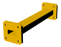
Short length of rectangular waveguide (WG17 with UBR120 connection-flanges)
|
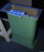
Section of flexible waveguide
|
Contents |
History
The first waveguide was proposed by J. J. Thomson in 1893 and experimentally verified by Oliver Joseph Lodge in 1894; the mathematical analysis of the propagating modes within a hollow metal cylinder was first performed by Lord Rayleigh in 1897. (McLachan, 1947.)
Principles of operation
Depending on the frequency, waveguides can be constructed from either conductive or dielectric materials. Generally, the lower the frequency to be passed the larger the waveguide is. For example the natural waveguide the earth forms given by the dimensions between the conductive Ionosphere and the ground as well as the circumference at the median altitude of the earth is resonant at 7.83 Hz. This is also known as Schumann resonance. Waveguides can also be less than a millimeter in width. An example might be those that are used in extremely high frequency (EHF) Satellite Communications(SATCOM).
Analysis
Electromagnetic waveguides are analyzed by solving Maxwell's equations, or their reduced form, the electromagnetic wave equation, with boundary conditions determined by the properties of the materials and their interfaces. These equations have multiple solutions, or modes, which are eigenfunctions of the equation system. Each mode is therefore characterized by an eigenvalue, which corresponds to a cutoff frequency below which the mode cannot exist in the guide.
Waveguide propagation modes depend on the operating wavelength and polarization and the shape and size of the guide. The longitudinal mode of a waveguide is a particular standing wave pattern formed by waves confined in the cavity. The transverse modes are classified into different types:
- TE modes (Transverse Electric) have no electric field in the direction of propagation.
- TM modes (Transverse Magnetic) have no magnetic field in the direction of propagation.
- TEM modes (Transverse ElectroMagnetic) have no electric nor magnetic field in the direction of propagation.
- Hybrid modes have both electric and magnetic field components in the direction of propagation.
In hollow waveguides (single conductor), TEM waves are not possible, since Maxwell's Equations will give that the electric field must then have zero divergence and zero curl and be equal to zero at boundaries, resulting in a zero field. (or, equivalently,  with boundary conditions guaranteeing only the trivial solution). However, TEM waves can propagate in coaxial cable because there are two conductors.
The mode with the lowest cutoff frequency is termed the dominant mode of the guide. It is usual to choose the size of the guide such that only this one mode can exist in the frequency band of operation. In rectangular and circular (hollow pipe) waveguides, the dominant modes are designated the TE1,0 mode and TE1,1 modes respectively.
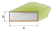
 TE1,0 mode of a rectangular hollow metallic waveguide. |
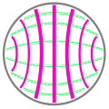 TE1,1 mode of a circular hollow metallic waveguide. |
Hollow metallic waveguides

In the microwave region of the electromagnetic spectrum, a waveguide normally consists of a hollow metallic conductor. Hollow waveguides must be one-half wavelength or more in diameter in order to support one or more transverse wave modes.
Waveguides are often pressurized to inhibit arcing/multipaction, allowing higher power. Conversely, waveguides may be required to be evacuated as part of evacuated systems. (e.g. electron beam systems)
A slotted waveguide is generally used for radar and other similar applications. The waveguide structure has the capability of confining and supporting the energy of an electromagnetic wave to a specific relatively narrow and controllable path.
A closed waveguide is an electromagnetic waveguide (a) that is tubular, usually with a circular or rectangular cross section, (b) that has electrically conducting walls, (c) that may be hollow or filled with a dielectric material, (d) that can support a large number of discrete propagating modes, though only a few may be practical, (e) in which each discrete mode defines the propagation constant for that mode, (f) in which the field at any point is describable in terms of the supported modes, (g) in which there is no radiation field, and (h) in which discontinuities and bends cause mode conversion but not radiation.
Hollow metallic waveguides are far narrower than the wavelength of operation. They can take the form of single conductors with or without a dielectric coating, e.g. the Goubou line and helical waveguides.
Voltage standing wave ratio (VSWR) measurements may be taken to ensure that a waveguide is contiguous and has no leaks or sharp bends. If such bends or holes in the waveguide surface are present, this may diminish the performance of both TX and RX equipment strings. Arcing may occur if there is a hole, if transmitting at high power (usually 200 watts or more). Waveguide plumbing[1] is crucial for proper waveguide performance. Reflected power may occur and damage equipment as well. Another cause for a bad VSWR in a waveguide is moisture build up, which can typically be prevented with silica gel, a desiccant. Due to the negative effect of moisture buildup within the waveguide, desiccant silica gel canisters may be attached with screw-on nibs.
Waveguide in practice
In practice, waveguides act as the equivalent of wires for high frequency circuits. For such applications, it is desired to operate waveguides with only one mode propagating inside of the waveguide. With rectangular waveguides, it is possible to design the waveguide such that the frequency band over which only one mode propagates is as high as 2:1 (i.e. the ratio of the upper band edge to lower band edge is 2). With circular waveguides, the highest possible band width allowing only a single mode to propagate is only 1.3601:1.[2]
Because rectangular waveguide have a much larger band width over which only a single mode can propagate, standards exist for rectangular waveguides, but not for circular waveguides. In general (but not always), standard waveguides are designed such that
- one band starts where another band ends, with another band that overlaps the two bands
- the lower edge of the band is approximately 30% higher than the waveguide's cutoff frequency
- the upper edge of the band is approximately 5% lower than the cutoff frequency of the next higher order mode
- the waveguide height is half the waveguide width
The first condition is to allow for applications near band edges; the second condition minimizes the impacts of dispersion, a phenomenon in which the velocity of propagation is a function of frequency; the third condition minimizes the probability of tunnelling of the next higher order mode; the fourth condition is the condition that allows a 2:1 band width of operation. Although it is possible to have a 2:1 band width of operation when the height is less than half the width, having the height exactly half the width maximizes the power that can propagate inside the waveguide before dielectric breakdown occurs.
Below is a table of waveguide standards. The waveguide name "WR" is an abbreviation for "Waveguide Rectangular", and the number is the width of the guide (in hundredths of inches)
| Waveguide name | Frequency Band Name | Recommended Frequency Band of operation (GHz) | Cutoff frequency for lowest order mode (GHz) | Cutoff frequency for next mode (GHz) | Inner dimensions of waveguide opening (inch) | ||
|---|---|---|---|---|---|---|---|
| EIA | RCSC | IEC | |||||
| WR650 | WG6 | R14 | 1.15 — 1.72 | 0.908 | 1.816 | 6.500 × 3.250 | |
| WR510 | WG7 | R18 | 1.45 — 2.20 | 1.157 | 2.314 | 5.100 × 2.550 | |
| WR430 | WG8 | R22 | 1.72 — 2.60 | 1.372 | 2.745 | 4.300 × 2.150 | |
| WR340 | WG9A | R26 | 2.20 — 3.30 | 1.736 | 3.471 | 3.400 × 1.700 | |
| WR284 | WG10 | R32 | 2.60 — 3.95 | 2.078 | 4.156 | 2.840 × 1.340 | |
| WR229 | WG11A | R40 | C band (part) | 3.30 — 4.90 | 2.577 | 5.154 | 2.290 × 1.145 |
| WR187 | WG12 | R48 | C band (part) | 3.95 — 5.85 | 3.153 | 6.305 | 1.872 × 0.872 |
| WR159 | WG13 | R58 | C band (part) | 4.90 — 7.05 | 3.712 | 7.423 | 1.590 × 0.795 |
| WR137 | WG14 | R70 | C band (part) | 5.85 — 8.20 | 4.301 | 8.603 | 1.372 × 0.622 |
| WR112 | WG15 | R84 | — | 7.05 — 10.00 | 5.260 | 10.520 | 1.122 × 0.497 |
| WR90 | WG16 | R100 | X band | 8.20 — 12.40 | 6.557 | 13.114 | 0.900 × 0.400 |
| WR75 | WG17 | R120 | — | 10.00 — 15.00 | 7.869 | 15.737 | 0.750 × 0.375 |
| WR62 | WG18 | R140 | Ku band | 12.40 — 18.00 | 9.488 | 18.976 | 0.622 × 0.311 |
| WR51 | WG19 | R180 | — | 15.00 — 22.00 | 11.572 | 23.143 | 0.510 × 0.255 |
| WR42 | WG20 | R220 | K band | 18.00 — 26.50 | 14.051 | 28.102 | 0.420 × 0.170 |
| WR34 | WG21 | R260 | — | 22.00 — 33.00 | 17.357 | 34.715 | 0.340 × 0.170 |
| WR28 | WG22 | R320 | Ka band | 26.50 — 40.00 | 21.077 | 42.154 | 0.280 × 0.140 |
| WR22 | WG23 | R400 | Q band | 33.00 — 50.00 | 26.346 | 52.692 | 0.224 × 0.112 |
| WR19 | WG24 | R500 | U band | 40.00 — 60.00 | 31.391 | 62.782 | 0.188 × 0.094 |
| WR15 | WG25 | R620 | V band | 50.00 — 75.00 | 39.875 | 79.750 | 0.148 × 0.074 |
| WR12 | WG26 | R740 | E band | 60.00 — 90.00 | 48.373 | 96.746 | 0.122 × 0.061 |
| WR10 | WG27 | R900 | W band | 75.00 — 110.00 | 59.015 | 118.030 | 0.100 × 0.050 |
| WR8 | WG28 | R1200 | 90.00 — 140.00 | 73.768 | 147.536 | 0.080 × 0.040 | |
| WR7 | WG29 | R1400 | 112.00 — 172.00 | 90.791 | 181.583 | 0.0650 × 0.0325 | |
| WR5 | WG30 | R1800 | 140.00 — 220.00 | 115.714 | 231.429 | 0.0510 × 0.0255 | |
| WR4 | WG31 | R2200 | 172.00 — 260.00 | 137.243 | 274.485 | 0.0430 × 0.0215 | |
| WR3 | WG32 | R2600 | 220.00 — 330.00 | 173.571 | 347.143 | 0.0340 × 0.0170 | |
For the frequencies in the table above, the main advantage of waveguides over coax cables is that waveguides support propagation with lower loss. For lower frequencies, the waveguide dimensions become impracticably too large, and for higher frequencies the dimensions become impracticably too small (the manufacturing tolerance becomes a significant portion of the waveguide size).
Dielectric rods for microwaves
Dielectric rod waveguides, in linear arrays of short transverse conductors, and planar resistive conductors use the same principle as optical waveguides.
These function via a refractive index effect where the waveguide slows the EM wave velocity below the free space velocity, continuously bending the relatively wide EM wavefronts towards the narrow waveguide and keeping them entrained. Helical waveguides and linear arrays of short conductors are used as part of "end-fire" antennas such as the helical antenna and Yagi antenna. Planar resistive waveguides are used in Over-The-Horizon radar and the Ground Wave Emergency Network, where the resistive surface of the Earth or ocean serves to slow the waves below free space velocity; entraining them and forcing them to follow the curvature of the Earth. Several waveguides based on entrainment of EM waves also exist.
See also
|
|
References
This article is based in part on material from Federal Standard 1037C and from MIL-STD-188, and ATIS
- ↑ 1.0 1.1 Institute of Electrical and Electronics Engineers, “The IEEE standard dictionary of electrical and electronics terms”; 6th ed. New York, N.Y., Institute of Electrical and Electronics Engineers, c1997. IEEE Std 100-1996. ISBN 1-55937-833-6 [ed. Standards Coordinating Committee 10, Terms and Definitions; Jane Radatz, (chair)]
- ↑ For band widths lower than 2:1 it is more common to express them as a percentage of the center frequency, which in the case of 1.3601:1 is 26.55%. For reference, a 2:1 band width corresponds to a 66.67% band width. The reason for expressing band widths as a ratio of upper to lower band edges for band widths greater than 66.67% is that in the limiting case that the lower edge goes to zero (or the upper edge goes to infinity), the band width approaches 200%, which means that the entire range of 3:1 to infinity:1 map into the range 100% to 200%.
- J. J. Thomson, Recent Researches (1893).
- O. J. Lodge, Proc. Roy. Inst. 14, p. 321 (1894).
- Lord Rayleigh, Phil. Mag. 43, p. 125 (1897).
- N. W. McLachlan, Theory and Applications of Mathieu Functions, p. 8 (1947) (reprinted by Dover: New York, 1964).
Further reading
- George Clark Southworth, "Principles and applications of wave-guide transmission". New York, Van Nostrand [1950], xi, 689 p. illus. 24 cm. Bell Telephone Laboratories series. LCCN 50009834
External links
- Patents
- Southworth, U.S. Patent 2,407,690, "Wave guide electrotherapeutic system"
- Hopper, U.S. Patent 2,806,138, "Wave guide frequency converter", September 10, 1957
- Websites